
Project Report - Part 2: Assembly
While our winter efforts focused on the sloping pit and divers, we were now fully engaged in assembling the new slitting line. However, before installation could begin, the hall floor presented us with some unexpected challenges.
Once again, it was the unseen portion of the substructure that caused concern. A geological assessment revealed a subsoil prone to settlement. To ensure the ground could support the weight of the multi-tonne system, 60 micropiles were driven up to 12 metres deep into the ground to reach stable layers. These piles were then filled with concrete and anchored to the new 630 m² floor slab, which now supports the longitudinal slitting line, and other equipment.
Video Report

Floor slab: Only 0.2 mm flatness tolerance over 30 m
As the new longitudinal slitting line allows for virtually no tolerances in its positioning or alignment, the floor slab beneath, up to 1 metre thick, must not shift due to dynamic forces or the equipment’s weight. To meet the required flatness tolerance of just 0.2 mm over 30 metres, 40 tonnes of reinforcing steel were embedded in the floor slab.
Cables and Lines Installed Below Ground Level
The pits for the lift units, which are recessed nearly 2 metres into the floor, also had to be constructed with millimetre precision. All cable ducts were embedded directly into the floor slab. Installing the electrical and service lines beneath ground level not only improves maintenance access but also enhances workplace safety.


Challenging Connection to Existing Hall Floor
Once the new floor slab was completed, the remainder of the hall floor was levelled. Years of use and the resulting loads had caused varying degrees of settlement in the existing flooring. To create a clean connection between the new and old surfaces, a 2-metre-wide section of the original floor covering had to be milled out. A transition was then created using monolithic concrete. This ensured logistical independence between the machine area and the storage facility.
Escape Tunnel Over 100 m Long
A key planning requirement for the build was the inclusion of an escape tunnel along the hall wall. Constructed from calcium silicate brick, it spans over 100 metres in length. In the event of a fire in the hall, it provides a secure evacuation route to the outside.


Surface Milling Machine at Its Limit
The new floor slab for the machinery was installed at the rear section of the hall. At the front of the hall, where raw materials are delivered, the original floor covering was still in place. Rather than removing and replacing it entirely, we opted to mill the surface. This task was carried out using a surface milling machine similar to those used in motorway construction. However, the heavily reinforced 1,200 m2 floor area in this part of the hall pushed the machine to its operational limits. At one point, work was nearly called off due to the extreme reinforcement. Nevertheless, the machine managed to complete its task. After milling, a roughly 3 cm thick monolithic concrete layer was applied. The result: a uniform floor surface throughout the entire hall.
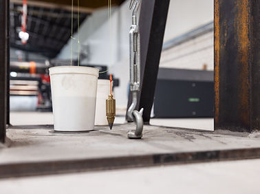
Assembly with Guide Lines and Plumb Bobs
While the milling machine was working its way through one half of the hall, the assembly of the longitudinal slitting line progressed in the other. To protect this sensitive work from the dust generated during milling, we installed a massive plastic barrier from ceiling to floor. A network of steel guide wires stretched above the machine, combined with traditional plumb bobs, ensured the system was positioned with maximum precision. This remains the most reliable method for aligning such equipment to within a tenth of a millimetre.

Outlook Is Encouraging
The construction work is complete and the system components are now in place. Currently, approximately 200 km of electrical cables are being laid and connected. The next step is programming the control system. We are confident that the system will be operational by the end of September.